


 Home
HomeGreece Kozani Solar Park(Kozani)
 GERITEL
 Apr 23,2026

Project Snapshot
A 204MW ground-mounted solar plant on the outskirts of Kozani, in Greece's Western Macedonia region. Commissioned in 2022. Developed by HELLENiQ ENERGY, EPC'd by Juwi Hellas. At the time, Europe's largest bifacial installation. Roughly 450 hectares split across 18 individual plots, over 500,000 bifacial modules, €130 million total investment. Annual generation: approximately 320 million kWh, enough for 75,000 households.
This is a look back at how the cable specification for that project came together—from the supplier side, and from the questions the EPC team actually cared about.
The Worry That Started Everything
The first call with the procurement lead did not begin with pricing. He opened with a story about a previous project in the Peloponnese: three years in, the PV cable jackets were chalking and cracking. Surface temperatures in Greek summer routinely hit 60–70°C. UV exposure was severe. Dust was constant. Kozani, he suspected, would be worse.
What he was really asking: can I trust these cables to last 25 years without becoming a maintenance nightmare across 450 hectares?
That question is not answered by a datasheet. It is answered by whether the supplier can produce evidence that survives independent verification. We provided TÜV certificate B 126326 0001 Rev.00 for our H1Z2Z2-K and PV1-F solar cable ranges. He looked it up himself in the TÜV Rheinland database. That single act—checking, rather than accepting—told me everything about his previous experiences with suppliers.
The technical explanation for why XLPO matters in this environment is straightforward but often glossed over. Standard PVC jacketing doubles its aging rate for every 7–10°C above 70°C. At Kozani, cable surface temperatures on black mounting structures can push toward 80–90°C. XLPO's polymer structure resists both UV-induced chain scission and thermal oxidation at these temperatures. Accelerated aging at 135°C for 6,000 hours still leaves tensile strength retention above 85%. Translated to field conditions, that maps to a service life envelope covering the 25-year design horizon.
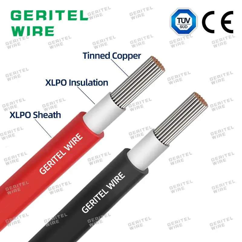
A detail that rarely makes it into RFQ responses: soil chemistry. Kozani's ground is alkaline, with sulfur compounds present. Bare copper conductors buried long-term in this chemistry develop oxide and sulfide layers that increase resistance and create hot spots under load. We use tin-plated copper. The tin layer is thin, but it blocks the electrochemical reaction. If someone digs up a sample in year 20, the conductor should still read metallic, not green.
Right Answer for the Edge Cases
The project used 550W bifacial modules, 26 per string, open-circuit voltage around 47V per module, roughly 1,220V per string. String inverters with MPPT windows of 850–1,500VDC. Combiner boxes were 24-in, 1-out.
For standard string lengths under 30 meters, H1Z2Z2-K 1×4 mm² DC1500V carries the ~13A string current with copper losses under 0.3%. That is comfortably inside any design threshold. Moving to 6 mm² would cut that loss by perhaps 0.1% but raise material cost by ~40%. On a project where cable length is measured in hundreds of kilometers, that delta is real money.
But two plots had edge arrays where string lengths stretched toward 40 meters because of terrain constraints. At that length, 4 mm² voltage drop approaches the 1% design limit. Summer heat raises conductor resistance another 4%. The combination puts you on the wrong side of the margin. For those specific edge strings, we switched to H1Z2Z2-K 1×6 mm² DC1500V. The extra cost is localized to maybe 5% of total string cable length, but it pulls the voltage drop back into the safe zone for the full 25-year operating envelope.
The logic is not "bigger is safer." The logic is: where the geometry of the array forces longer runs, the physics of resistance demands larger copper. Everywhere else, standard sizing preserves capital for things that matter more.
Where Current Aggregation Changes the Rules
Post-combiner, the game changes. Twenty-four strings at 13A each is 312A. The combiner-to-inverter trunk now sees serious current, and the distance matters more because the absolute voltage drop in volts scales with both current and resistance.
For runs under 50 meters, H1Z2Z2-K 1×10 mm² DC1500V holds voltage drop around 0.8%. At 150 meters, 10 mm² is no longer enough—drop exceeds 1.5%. We moved those longer trunks to 1×16 mm².
Then there was the 800-meter plot. Even 16 mm² as a single run was marginal. We proposed splitting into two parallel 16 mm² circuits rather than one 25 mm². The EPC team preferred this because 25 mm² has a bending radius requirement of roughly 40 cm—difficult to pull through conduit in rocky terrain, and slower to terminate. Two 16 mm² circuits hit the electrical target without creating a construction bottleneck.
This is the kind of decision that does not show up in a standard product catalog. It only emerges when the supplier asks about actual site distances before quoting.
Why 70 mm² Was Not Enough for Every Circuit
The AC side runs from inverter to step-up transformer at low voltage. With two 196kW inverters paralleled into one transformer, the AC current is approximately 560A.
The cost engineer wanted to standardize on YJV 3×70 mm² + 35 mm² PE for the entire AC network. It is the natural first choice—rated for typical loads, well-understood, competitively priced.
We pushed back on the dual-inverter circuits. Underground installation in Greek summer soil at 35°C, with soil thermal resistivity around 1.0 K·m/W, derates the ampacity of 70 mm² to roughly 522A. That is 107% of nominal load. The conductor runs hotter than the 90°C XLPE insulation limit. Insulation aging accelerates. Life expectancy drops from 25 years toward perhaps 15.
Upgrading to YJV 3×120 mm² + 70 mm² PE drops the load ratio to 72%, conductor temperature to roughly 75°C, and puts insulation aging back on the design curve. The upfront premium is about 35%. But replacement cost—excavation, extraction, re-laying, re-termination, plus generation loss during outage—would exceed that premium by an order of magnitude if it happens in year 15. And the EBRD financing agreement has equipment lifetime requirements that are not suggestions.
The 120 mm² specification was approved. Not because we argued harder, but because the total-cost-of-ownership math was unambiguous.
For a few long-distance AC feeders where voltage drop became the binding constraint rather than ampacity, we went to YJV 3×185 mm² + 95 mm² PE. These were the exception, not the rule—maybe 8% of total AC cable length.
The Layer Most PV Cable Suppliers Forget
A 204MW plant does not connect to the grid at low voltage. The 18 plots feed into a collection substation at 33kV, then into the Greek national grid via IPTO.
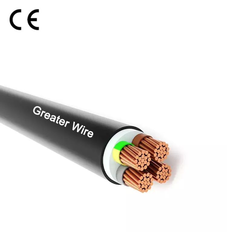
We supplied 33kV medium-voltage cables in 3×70 mm² and 3×120 mm² configurations. The construction here is fundamentally different from LV cable: copper conductor, XLPE insulation, semiconducting screens to grade the electric field and prevent partial discharge, metallic screen for earth-fault current, and steel tape armoring for mechanical protection during direct burial.
The semiconducting layer deserves more attention than it usually gets. At 33kV, any irregularity at the conductor-insulation interface creates electric field concentration. Without a semiconducting screen, micro-voids or protrusions become sites of partial discharge, which erodes the XLPE over months and years until failure. This is not a theoretical concern—it is the dominant failure mode in improperly manufactured MV cable.
The armoring addressed a specific Kozani site condition: several plots have rocky subsoil. Non-armored cable is cheaper by ~15%, but pulling it through trenches with stone content risks sheath damage. Damage to the outer layer in an MV cable does not cause immediate failure; it creates a moisture path to the metallic screen, which corrodes, which raises screen resistance, which reduces fault-current capacity, which eventually creates a safety hazard. One competitor proposed non-armored. It was rejected before the technical review meeting ended.
The Control Cable Problem That Appeared Late
During design review, the SCADA system was experiencing intermittent dropouts. The inverter manufacturer blamed cabling. The cabling supplier blamed inverter EMI.
The root cause was simpler than the argument: the control cables had no shielding. Several hundred string and central inverters switching at high frequency generate substantial conducted and radiated noise. Unshielded H05VV-F control cable over runs exceeding 100 meters picks up enough induced voltage to corrupt Modbus signaling.
We proposed replacing the standard H05VV-F 12×1.5 mm² with a custom version adding aluminum foil shielding plus a drain wire. Lead time extended by two weeks. Cost increased ~20%. The EPC accepted on one condition: if the problem persisted after replacement, we would bear responsibility for further remediation.
The dropouts stopped. The additional cost was under €8,000. The avoided cost—dispatching technicians to 18 scattered plots to troubleshoot communication faults—would have exceeded that figure on the first site visit alone.
Matching Construction Cadence, Not Warehouse Convenience
The 18 plots did not break ground simultaneously. Some were ready for electrical work while others awaited civil completion or permitting. A single bulk delivery would have forced the EPC to manage temporary storage, weather protection, and inventory sorting across a 450-hectare active construction zone.
We structured delivery in six batches, each aligned with the electrical installation schedule of two to three plots. Every cable drum was labeled with plot number, application, and specification: for example, "Block-3 / DC String / 4 mm² Red." This eliminated warehouse sorting time and let installation crews pull material directly to the correct array field.
During summer 2021, port congestion at Piraeus threatened to delay the fifth batch. We rerouted through Thessaloniki and arranged direct trucking to Kozani at our own additional expense—roughly €400 in extra freight. The cargo arrived on the original committed date. The EPC later noted that this flexibility prevented a cascading delay to string wiring on two plots that would have otherwise sat idle waiting for material.
What the Absence of Problems Suggests
The plant entered commercial operation in April 2022. No formal cable-specific operational report exists—large plants do not typically publish such documents—but feedback from the EPC and public generation data indicate the design assumptions have held:
No thermal derating or trip events attributed to cable overheating during peak summer conditions. System efficiency remains near design targets, suggesting the bifacial gain is being transmitted without excessive DC loss. SCADA communication has remained stable without recurring dropouts. Ground fault monitoring has not flagged abnormal leakage currents.
For cable infrastructure, the absence of incidents is the most meaningful performance metric.
Why This Specification Was Selected: The Client's Own Summary
In a post-project conversation, the procurement lead offered two observations that stuck with me.
First: we were the only supplier who asked for inverter-to-transformer distances per plot before submitting a proposal. Others sent price lists or asked only for total meterage. Distance determines whether 70 mm² or 120 mm² is the correct AC specification. Without that data, a proposal is guesswork dressed as engineering.
Second: the verifiability of the TÜV certificate mattered more than the certificate itself. He had checked ours. He had checked two competitors. Ours was real and covered the quoted variants. One competitor's certificate did not exist in the database. The other's covered a different product family. For an EBRD-financed project, that distinction separates passable suppliers from qualified ones.
If You Are Planning Something Similar
The Greek solar market is not defined by gigawatt-scale projects like Spain or the Middle East. It is characterized by fast permitting, rapid capital turnover, and investor sensitivity to lifecycle cost. Projects in the 5–50MW range dominate, with occasional larger developments like Kozani. The common thread is the environment: high summer temperatures, intense UV, and alkaline soils that punish materials not selected for endurance.
If you are developing in Greece, Italy, Spain, or similar southern European markets—or if your EPC team is facing a compressed schedule on a large-scale plant—we would welcome a conversation. We do not begin with a price list. We begin with questions about your module layout, inverter configuration, plot distances, and grid connection voltage. Then we explain which specifications are necessary investments, which can be optimized, and the physics behind each recommendation.
Dongguan GERITEL Electrical Co., Ltd.
Tel / WhatsApp / WeChat: +86 135 1078 4550 / +86 136 6257 9592
Email: manager01@greaterwire.com
 Bulgaria Verila Solar Park 124MW PV Plant



 Building 2, No. 40 Luxi 2nd Road, Liaobu Town, Dongguan City, Guangdong Province, China