


 Home
HomeCable Tray System Design Guide for Industrial Power and Control Networks
 GERITEL
 Jun 11,2026

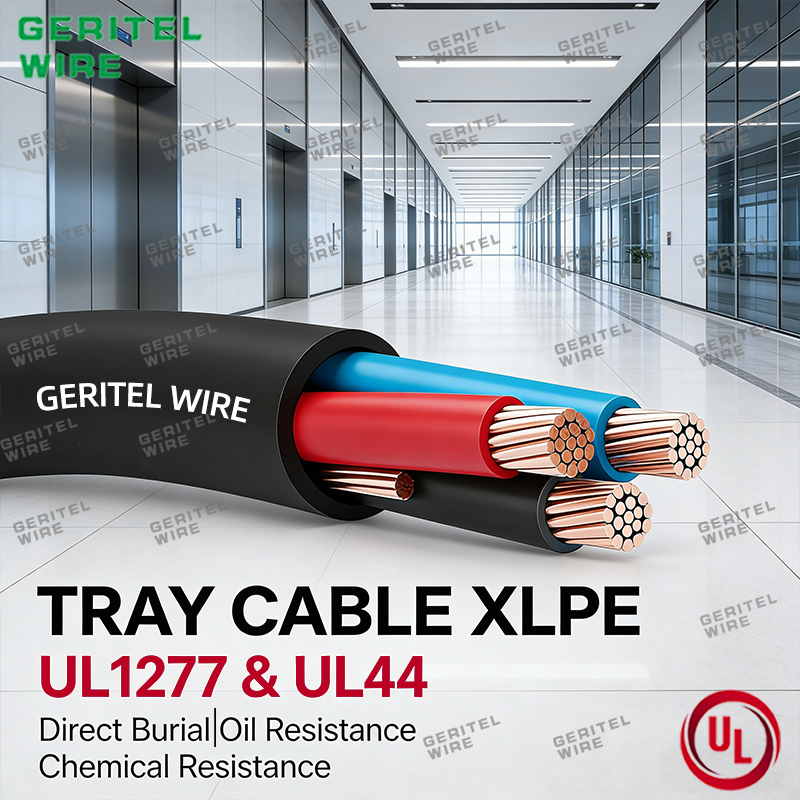
Industrial cable tray systems are the core load-bearing and routing infrastructure for all factory power distribution, automation control, and precision instrument signal transmission. Unlike simple conduit wiring, tray-based layouts support expandable, maintainable, and well-ventilated cable deployment, which is critical for long-term stable operation of industrial electrical systems. Poor tray structural matching, unreasonable layered partitioning, and ignored environmental adaptability often cause cable overheating, signal crosstalk, insulation aging, and even on-site inspection failures. This comprehensive design guide focuses on standardized pairing rules between tray structures and dedicated TC-ER power cable, targeting manufacturing plant harsh working conditions. It delivers practical, code-compliant design solutions for indoor outdoor TC-ER cable, instrumentation TC-ER cable, and hazardous-location Class 1 Division 2 TC-ER cable, helping engineers avoid common layout pitfalls and optimize industrial power and control network layouts.
1. Matching Cable Tray Structures with TC-ER Power Cable Specifications
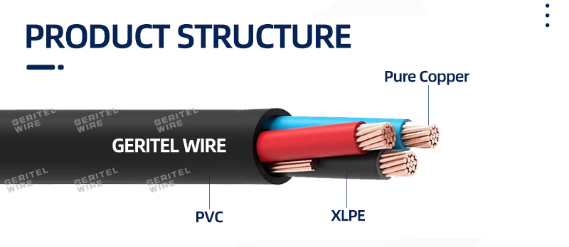
The primary principle of industrial tray design is structural adaptation to cable current load, outer jacket performance, and application attributes. Different types of TC-ER cables require corresponding tray support and heat dissipation structures; mismatched configurations will directly reduce cable ampacity and accelerate service life attenuation.
Ladder-type cable tray is the exclusive optimal structure for heavy-duty main power trunk lines. Designed with open rungs and high vertical side rails, it provides maximum cross-ventilation space, perfectly solving the heat dissipation problem of large-capacity 500 kcmil TC-ER cable in long-term full-load operation. In manufacturing plant main power distribution systems, this open structure avoids heat accumulation of high-current power cables and eliminates hidden dangers of insulation thermal aging, which cannot be replaced by closed tray structures.
Ventilated tray rack with uniform perforated bottom panels is customized for dense signal and precision monitoring circuits. It is specially applicable to bundled instrumentation TC-ER cable layout. The microporous ventilation design ensures overall heat dissipation of multi-core signal cables while preventing small-gauge flexible cables from sagging and deformation, maintaining neat and standardized wiring for factory detection and feedback loops.
Solid bottom cable tray provides full physical enclosure and isolation protection, serving as the standard layout carrier for harsh-environment TC-ER cables. It effectively shields external dust, mechanical impact, and corrosive substances, creating a stable internal wiring environment for industrial cables operating in complex factory scenarios.
2. Environmental Adaptation Design for Multi-Scenario Industrial TC-ER Tray Wiring
Manufacturing factories feature diverse and complex operating environments, including indoor high-load production areas, outdoor overhead trunk lines, and low-temperature regional workshops. Tray system design must fully cooperate with the environmental resistance attributes of indoor outdoor TC-ER cable to achieve long-term reliable operation.
For conventional indoor production workshops with normal temperature and humidity, standard galvanized tray systems can fully match the basic operating requirements of TC-ER power and control cables. For outdoor crossing sections and factory boundary trunk lines exposed to natural weather changes, the tray layout must reserve anti-aging and drainage structures to cooperate with indoor outdoor TC-ER cable' s dual weather resistance performance, preventing jacket cracking caused by long-term sun exposure and rain erosion.
For northern low-temperature factory workshops and outdoor winter wiring scenarios, ordinary cable layouts are prone to insulation brittleness and fracture. The tray support spacing and fixing methods need to be optimized to adapt to cold weather TC-ER cable’s low-temperature tolerance characteristics, avoiding cable damage caused by mechanical extrusion and vibration in low-temperature environments.
3. EMI Suppression Design for Instrumentation TC-ER Cable Tray Layout
Electromagnetic interference between power cables and weak-current signal cables is one of the most frequent and difficult-to-diagnose faults in industrial automation systems. Unreasonable tray partitioning leads to distorted instrument signals, floating data, and intermittent equipment operation failures, seriously affecting production stability.
In mixed power and control tray systems, strict physical partitioning isolation must be implemented. All high-current TC-ER power cable trunk lines are centrally arranged in independent tray zones, while precision instrumentation TC-ER cable for temperature, pressure, and flow monitoring is placed in isolated weak-current compartments. This segmented layout completely cuts off high-frequency electromagnetic radiation generated by power cables, ensuring the accuracy and stability of weak signal transmission.
In high-precision automated production lines, layered vertical tray installation is recommended: power cable trays are arranged on the upper layer, and instrument signal cable trays are placed on the lower layer, forming a three-dimensional anti-interference wiring structure, which further optimizes the transmission environment of instrumentation TC-ER cables.
4. Explosion-Proof Tray Wiring Rules for Class 1 Division 2 TC-ER Cable
Partial zones of manufacturing plants involve flammable dust and volatile gas environments, belonging to typical hazardous industrial locations, which have mandatory explosion-proof requirements for tray wiring systems.
Class 1 Division 2 TC-ER cable is the designated wiring product for factory hazardous zones, and its tray matching design has strict industry specifications. The tray system must adopt fully enclosed, dust-proof and anti-static structural configurations to avoid friction and impact sparks caused by cable shaking. Meanwhile, the tray laying height, gap distance and fixed density must comply with explosion-proof electrical standards, preventing external dangerous media from accumulating around the cables and eliminating explosion safety hazards.
It is strictly prohibited to mix ordinary non-explosion-proof TC-ER cables with Class 1 Division 2 TC-ER cable in the same partition of hazardous-area trays, which will directly lead to project inspection failure and potential safety risks.
5. Key Design Differences Between Indoor and Outdoor TC-ER Cable Tray Systems
Many design engineers adopt unified tray layout schemes for indoor and outdoor wiring, ignoring the performance differences of indoor outdoor TC-ER cable in different environments, resulting in inconsistent service life of internal and external wiring systems.
Indoor tray design focuses on heat dissipation and anti-interference, prioritizing ventilated and ladder structures to adapt to dense cable layout and long-term high-load operation. Outdoor tray design takes weather resistance and structural stability as the core, requiring reinforced anti-corrosion treatment, matched with closed protective accessories, to give full play to the outdoor anti-aging advantages of indoor outdoor TC-ER cable.
In addition, outdoor tray systems need to add waterproof and drainage structures to prevent rainwater accumulation from soaking cable jackets, avoiding premature aging and peeling of cable outer layers.
6. Common Tray Design Mistakes Causing TC-ER Cable Aging & Failure
Summarizing a large number of industrial wiring project cases, most cable aging and failure problems are not caused by product quality, but by unscientific tray design and layout.
The first common mistake is overcrowded tray wiring. Excessively dense cable bundles block the natural ventilation of ladder and ventilated trays, resulting in continuous heat accumulation of TC-ER power cable, long-term over-temperature operation, and accelerated insulation aging.
The second mistake is no partition for mixed strong and weak current circuits. Unisolated power cables and instrumentation TC-ER cable cause long-term electromagnetic interference, leading to signal instability and even cable insulation breakdown in severe cases.
The third mistake is mismatched tray structure for special environments. Using open trays for low-temperature and outdoor zones fails to protect cold weather TC-ER cable and indoor outdoor TC-ER cable, causing jacket damage and performance attenuation.
The fourth mistake is non-standard wiring in hazardous areas. Ordinary trays replace explosion-proof supporting structures for Class 1 Division 2 TC-ER cable, which fails to meet site safety and code requirements.
7. Practical FAQs for Industrial TC-ER Cable Tray System Engineering Design
Q1: What tray structure is most suitable for large-capacity industrial main power TC-ER cables?
A: Ladder-type cable tray is the best choice for large-specificationTC-ER power cable such as 500 kcmil models. Its open structure provides excellent heat dissipation, effectively avoiding thermal overload during long-term full-load operation of main trunk lines.
Q2: How to avoid signal interference of instrumentation TC-ER cables in tray layout?
A: Adopt segmented partition and layered layout design. Isolate instrumentation TC-ER cable from high-power TC-ER power cables physically to block electromagnetic crosstalk and ensure precision signal transmission.
Q3: What are the layout requirements for indoor outdoor TC-ER cable in tray systems?
A: Indoor parts focus on heat dissipation and anti-interference, while outdoor parts need anti-corrosion, waterproof and sun-proof tray protection structures to adapt to complex weather environments.
Q4: Is dedicated tray design required for Class 1 Division 2 TC-ER cable?
A: Yes. Hazardous areas must use explosion-proof fully enclosed tray structures, and mixed laying with ordinary cables is prohibited to meet industrial explosion-proof safety specifications.
Professional TC-ER Cable Tray Layout Solutions for Industrial Projects
Scientific cable tray system design is the key to ensuring the long-term safe and stable operation of industrial power and control networks. Reasonable matching of tray structures with TC-ER power cable, instrumentation TC-ER cable, indoor outdoor TC-ER cable and Class 1 Division 2 TC-ER cable can effectively avoid common engineering problems such as cable overheating, signal interference, insulation aging and non-compliant acceptance. We provide full-spec industrial TC-ER cable supporting solutions for manufacturing plant conventional workshops, low-temperature zones, outdoor trunk lines and hazardous explosion-proof areas. Contact our engineering team to obtain customized tray wiring design suggestions and cable specification matching schemes for your industrial projects.
Contact us
Dongguan Greater Wire & Cable Co., Ltd.
Tel/WhatsApp/Wechat: +86 136 6257 9592
Tel/WhatsApp/Wechat: +86 135 1078 4550
Email: manager01@greaterwire.com
Website: www.geritelgroup.com
 Understanding Equipment Wiring Cable Requirements in Industrial Machinery


 Building 2, No. 40 Luxi 2nd Road, Liaobu Town, Dongguan City, Guangdong Province, China